This is a PLC Program to Operate Stamping of Parts.
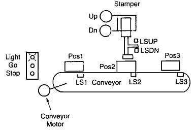
When a part is placed on the conveyor at position 1, and when a start button is pressed it moves to position 2. Upon reaching position 2, it stops for the stamping operation to take place. After stamping it automatically moves to position 3. It stops at position 3, where the part is removed manually from the conveyor. Assume only one part is on the conveyor at a time. Add limit switches, interlocks, push buttons, etc. as required.
- Assuming all the contacts available are of Normally Open type.
- Push Buttons to Start and Stop the process in case of malfunctioning.
- Use of Level Switches to detect the positions 1, 2 and 3 as shown as LS1, LS2 and LS3 respectively.
- Reversible motor with UP_MOTOR coil for reverse direction and DN_MOTOR coil for forward direction control.
- Conveyor Motor to move the part from position 1 to 2 and after stamping, 2 to 3.
- LSDN and LSUP are two other limit switches which detect the lower most and upper most position of the stamper arm.
- Additional use of relay contacts in the software during programming to store the various bits in order to run Motor continuously.
- Interlocking by using XIC contacts in the software in order to prevent from Malfunctioning.
Here is PLC program to Operate Stamping of Parts, along with program explanation and run time test cases.
List of Inputs & Outputs with addresses
I:0/0  = Start  					(Input)
I:0/1  = Stop		 				(Input)
I:0:2  = Level Switch to detect position 1 		(Input)
I:0/3  = Level Switch to detect position 2		(Input)
I:0/4  = Level Switch to detect position 3		(Input)
I:0/6  = Level Switch to detect lower most position 	(Input)
I:0/5  = Level Switch to detect upper most position	(Input)
O:1/10 = Motor coil for reverse direction rotation	(Output)
O:1/11 = Motor coil for forward direction rotation	(Output)
Ladder Logic Diagram for the given problem is shown below.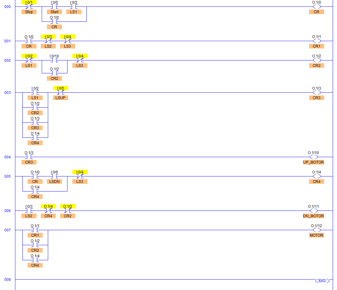
- Rung000- When start button is pressed and position 1 is detected by LS1, CR1 relay goes ON and is latched.
- Rung001- As long as CR is high, it latches CR1 and CR1 sends continuous true pulse to O:0/12 of Rung007 which energizes motor coil starting the MOTOR. This MOTOR is stopped only when LS2 and/or LS3 are detected.
- Rung002- CR2 is used when the process is stuck in the middle. In this case, manual switch with address I:0/10 is used to restart the MOTOR.
- Rung003- CR3 is energized whenever LS1, CR2 or CR4 goes high. CR3 relay is used to operate the UP_MOTOR coil of the stamping motor.
- Rung004- UP_MOTOR coil is energized due to CR3 and stamper comes in the main position. This is de-energized when LSUP is detected which is the upper most and main position of the stamper.
- Rung005- When stamping is done that is when lower most position is detected, CR4 is energized and latched starting the MOTOR until LS3, position 3 of the part is detected.
- Rung006- DN_MOTOR coil is energized in order to stamp the part which is when LS2, position 2 of the part is detected. It stays de-energized whenever CR4 (CR*LSDN) and CR2 (MOTOR) are ON/Energized.
- Rung007- Conveyor belt is started whenever MOTOR coil is energized that is whenever LS1 and LSDN is detected that is whenever Position 1 is detected and again when stamping is done.
- Rung008- End of the program and the scan cycle is repeated scanning from the Rung 000 again.
Input	        Relay Outputs   	MOTOR
LS1=1,Start=1	CR=ON, CR1=ON, CR3=ON	ON
LS2=1   	CR1=OFF, CR3=OFF	OFF
Input	        Relay Outputs	UP_MOTOR DN_MOTOR
LSDN=1,LS3=0	CR4=1	        OFF	 OFF
LSUP=0,LS1=1	CR3=1	        ON	 OFF
LS2=1	        C2=0,C4=0       OFF	 ON
Sanfoundry Global Education & Learning Series – PLC Algorithms.
To practice all PLC programs, here is complete set of 100+ PLC Problems and Solutions.
