This is a PLC Program to Operate Drilling of Parts.
Problem Description
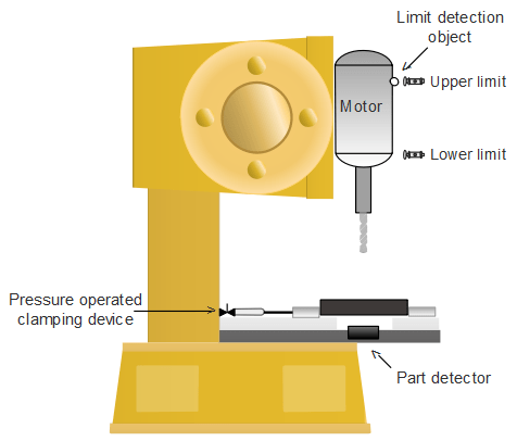
Whenever a part is placed on the drilling table, pneumatic clamper clamps the part and drilling process is done. When drilling is done, clamper releases the part by releasing pressure. When another part is detected, the process is repeated. Implement this in PLC using Ladder Diagram programming language.
Problem Diagram
Problem Solution
- Set lower and upper limit of a motor to stop and start the drilling process. This is done for precise drilling and to obtain uniformity.
- Pressure operated clamping device is used to hold the objects firmly. This is operated by 20psig air supply which is provided when an object is detected.
- Limit detection object is placed on the motor to detect upper and lower limit by the switches.
PLC Program
Here is PLC program to Operate Drilling of Parts, along with program explanation and run time test cases.
List of Inputs and Outputs
 I:1/14	= Start			(Input)
 I:1/15	= Stop			(Input)
 O:2/15	= master coil		(Output)
 O:2/0	= Clamping Device	(Output)
 O:2/1	= Drilling Motor	(Output)
 O:2/2	= Motor Down		(Output)
 O:2/3	= Motor Up		(Output)
 I:1/0	= Object detect switch	(Input)
 I:1/1	= Lower Limit		(Input)
 I:1/2	= Upper Limit		(Input)
Ladder Diagram to implement automation of drilling process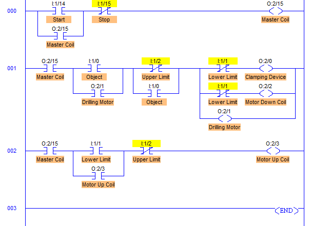
advertisement
advertisement
Program Description
- RUNG001 is to operate Clamping device with address O:2/0, Motor Down Coil O:2/2 and Drilling Motor O:2/1.
- These outputs are operated when an object is detected.
- Clamping device and Motor Down coil is de-energized when Lower Limit of drilling motor is detected which is connected to I:1/1. And Drilling Motor O:2/1 is de-energized when Upper Limit I:1/2 is detected.
- RUNG002 is to operate Motor Up coil with address O:2/3. When Lower limit is reached that means drilling is completed. Next operation is to take Drilling motor back to its main position and for that reverse coil Motor Up coil with address O:2/3 is energized.
- When it is reached to its main position that is Upper Limit I:1/2, reversing Motor Up coil is de-energized.
Runtime Test Cases
Inputs	    Outputs	               Physical Elements
I:1/0 = 1   O:2/0 = O:2/1 = O:2/2 = 1  Activate Clamper, ON Motor, Energize Motor Down
I:1/1 = 1   O:2/0 = 0, O:2/2 = 0       Deactivate Clamper, De-Energize Motor Down
I:1/1 = 1   O:2/3 = 1	               Energize Motor Up Coil
I:1/2 = 1   O:2/3 = 0	               De-Energize Motor Up Coil, OFF Motor
Sanfoundry Global Education & Learning Series – PLC Algorithms.
To practice all PLC programs, here is complete set of 100+ PLC Problems and Solutions.
