This is a PLC Program to Implement SR Flip-Flop.
Problem Description
To Implement SR Set-Reset Flip Flop in PLC using Ladder Logic programming language.
Problem Solution
- SR Flip-Flop is also known as Latch since it is capable of locking the information.
- In many PLC vendors like Siemens, Omron and many others, SR Flip Flop is included as an instruction in the instruction set. So no logic is required to implement SR Flip Flop in such PLCs.
- In Omron PLCs, you can develop the same logic using KEEP instruction.
- K-map solving is again not required to solve this problem.
- By observing Truth table of SR Flip Flop, required output is obtained in accordance with the input provided and bits storing.
- Truth table relating SR Flip Flop is given below.
The SR flip flop first executes the set instruction and then reset instruction, so the address remains reset for the remainder of program scanning.
Truth Table relating to SR Flip Flop
Inputs  Outputs
S    R	Q Q^	Qn+1 Q^n+1
0    0	0 1	0    1
0    0	1 0	1    0
0    1	0 1	0    1
0    1	1 0	0    1
1    0	0 1	1    0
1    0	1 0	1    0
1    1	0 0	x    x
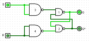
Realization of S-R Latch using Logic Gates
PLC Program
advertisement
advertisement
Here is PLC program to Implement SR Flip-Flop, along with program explanation and run time test cases.
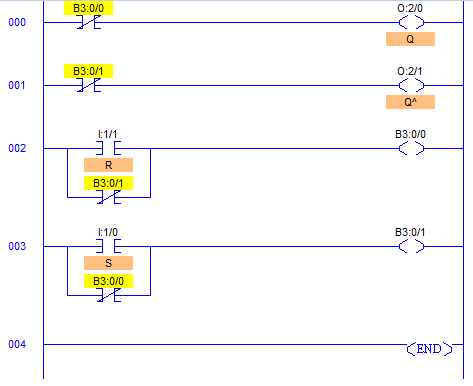
List of Inputs and Outputs
 Set	   =		I:1/0	(Set Input)
 Reset	   =		I:1/1	(Reset Input)
 Q (Set)   =		O:2/0	(Q Output)
 Q^(Reset) =		O:2/1	(Q^ Output)
 Qn+1	   =		B3:0/0	(Relay Bit)
 Q^n+1	   =		B3:0/1	(Relay Bit)
Ladder Diagram to obtain output
Program Description
- By definition, a condition of Q (O:2/0) = 1 and Q^ (O:2/1) = 0 is Set and a condition of Q (O:2/0) = 0 and Q^ (O:2/1) = 1 is Reset.
- If the signal state is high at input I:1/0 and low at I:1/1, bit B3:0/1 is set and output O2:0/0 is set to 1 which is a SET condition of this logic.
- Otherwise, if the signal state at input I:1/0 is low and at input I:1/1 is high, bit B3:0/1 is reset and output O:2/0 is reset which is a RESET condition of this logic.
- During power up, when both the inputs are low, Q (O:2/0) will go high because of its order.
- And after either of the states is achieved, if both signal states go low, nothing is changed which is latched state.
- If both signal states are set to high, the Q^ output O:2/1 instruction dominates because of the order in the ladder diagram, B3:0/1 is low and B3:0/0 is high causing Q output O:2/0 to reset.
- When S I:1/0 and R I:1/1 both are equal to 0, the outputs “latch” in their prior states.
- Slight delay may occur in inputs and resulting changes in outputs due to PLC’s program scan time.
Runtime Test Cases
Input	        Output
S	R	Q	Q^
0	0	Latch	Latch
0	1	0	1
1	0	1	0
1	1	0	0
Sanfoundry Global Education & Learning Series – PLC Algorithms.
To practice all PLC programs, here is complete set of 100+ PLC Problems and Solutions.
advertisement
If you find any mistake above, kindly email to [email protected]
