This is a PLC Program to Implement D Flip Flop.
Problem Description
Implementing D Flip Flop in PLC using Ladder Logic programming language.
Problem Solution
- This latch has only 1 input denoted as D.
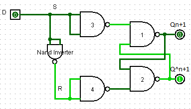
- D latch is the simple gated S-R latch with a NAND inverter connected between its S and R inputs.
- In S-R Flip Flop when S=R=0 or S=R=1, the outputs Q and Q^ either don’t change or they are invalid (indeterminate) due to race condition.
- This disadvantage of S-R latch can be overcome by using the D latch.
- As we can see in the diagram below, S and R inputs will always be the complements of each other. Hence S = R = 0 or S = R = 1 condition will never occur. This will avoid the problems associated with S-R=0-0 and S-R=1-1 conditions.
- Truth table can be obtained as given below
Truth Table for the D Latch
Inputs	Outputs	        Comment
D	Qn+1	Q^n+1
0	0	1	Reset Condition
1	1	0	Set Condition
Realization of D Latch using Logic Gates
PLC Program
Here is PLC program to Implement D Flip Flop, along with program explanation and run time test cases.
advertisement
advertisement
List of Inputs and Outputs
D (Set)	 =	I:1/0	(Set Input)
D (Reset)=	I:1/0	(Reset Input)
Qn+1     =	O:2/0	(Q Output)
Q^n+1    =	O:2/1	(Q^ Output)
Bit 0    =	B3:0/0	(Bit 0 output)
Bit 1    =	B3:0/1	(Bit 1 output)
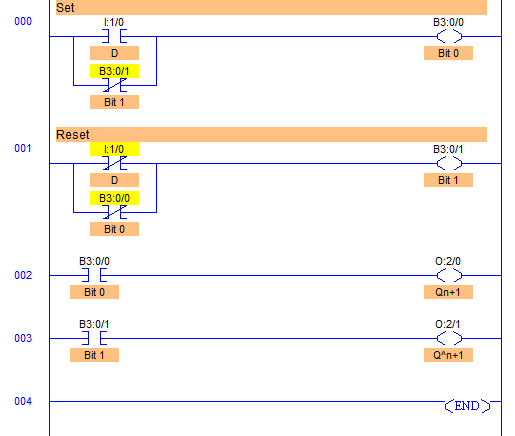
Ladder Diagram to obtain output
Program Description
- By definition, a condition of Qn+1 = 1 and Q^n+1 = 0 is Set and a condition of Qn+1 = 0 and Q^ n+1 = 1 is Reset.
- As we can see from the circuit diagram as well as in the ladder diagram, the only difference between S-R latch and D Latch is that it uses it uses inverted value of S.
- So as we can see in the ladder diagram, R is replaced by inverted input of D (Set) I:1/0 and denoted as D (Reset) I:1/0.
- During power up, Q^n+1 (O:2/1) will go high because of its order scan cycle follows.
- In a D latch, we can simply say that when we activate the D input I:1/0 sets the circuit, and when we de-activate the D input I:1/0 resets the circuit.
- Both signal states can never be set to high as the Reset input is replaced by Inverted input of D I:1/0, so Race Condition is eliminated.
- Slight delay may occur in inputs and resulting changes in outputs due to PLC’s program scan time which is unobtrusive.
Runtime Test Cases
Inputs	Outputs	        Comment
D	Qn+1 Q^n+1
0	0    1          Reset Condition
1	1    0	        Set Condition
Sanfoundry Global Education & Learning Series – PLC Algorithms.
To practice all PLC programs, here is complete set of 100+ PLC Problems and Solutions.
