This is a PLC Program to Implement a Combinational Logic Circuit (1).
The input to combinations logic circuit is a 4-bit binary number. Design the logic circuit with two outputs (Y1, Y2) for the following conditions. Also develop PLC program in Ladder Logic for the same.
Y1=1 if the input binary number is 5 or less than 5.
Y2=1 if the input binary number is 9 or more than 9.
- To solve this problem, first the table showing ON state of Y1 and Y2 is created. (When Y1 or Y2 is 1).
- According to the table designed, Y1 and Y2 both will have different equations, Y1 when input binary number is 5 or less than 5 and Y2 when input is 9 or more than 9.
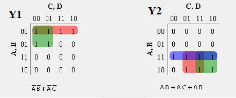
- To obtain these equations, Karnaugh-Map method is again used.
- By solving output expressions, we obtained minimized form of equation which is then applied into Ladder Diagram.
Output table and Karnaugh-Map method to solve Y1 and Y2 equations
Binary Inputs	                Outputs
A	B	C	D	Y1	Y2
0	0	0	0	1	0
0	0	0	1	1	0
0	0	1	0	1	0
0	0	1	1	1	0
0	1	0	0	1	0
0	1	0	1	1	0
0	1	1	0	0	0
0	1	1	1	0	0
1	0	0	0	0	0
1	0	0	1	0	1
1	0	1	0	0	1
1	0	1	1	0	1
1	1	0	0	0	1
1	1	0	1	0	1
1	1	1	0	0	1
1	1	1	1	0	1
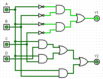
Combinational Circuit for outputs expressed using logic gates.
Here is PLC program to Implement a Combinational Logic Circuit, along with program explanation and run time test cases.
List of Inputs and Outputs
A =			I:1/0	(Input)
B =			I:1/1	(Input)
C =			I:1/2	(Input)
D =			I:1/3	(Input)
Y1=			O:2/0	(Output)
Y2=			O:2/1	(Output)
Ladder Diagram to obtain combinational logic circuit output.
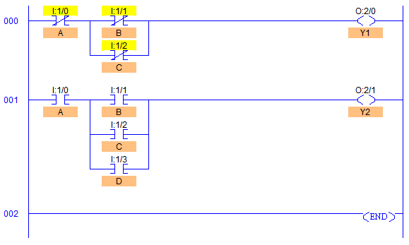
- Rung000 is to generate output Y1 which is 1 goes high or is set to 1 when Input Binary Number is 5 or less than 5.
- Rung001 is to generate output Y2 which goes high or is set to 1 when Input Binary Number is 9 or more than 9.
- In the given program, parallel connection shows ORing of inputs and series connection shows ANDing of inputs.
- Hence, output Y1 goes High/1 if any of the two conditions is fulfilled, whenever A (I:1/0) and B (I:1/1) both are Low/0 or whenever A (I:1/0) and C (I:1/2) both are Low/0.
- And accordingly, output Y2 goes high if any of the following conditions is fulfilled,
A (I:1/0) and B (I:1/1) both are High/1.
A (I:1/0) and C (I:1/2) both are High/1.
A (I:1/0) and D (I:1/3) both are High/1.
Input
Number	Binary Inputs	                Outputs
	A	B	C	D	Y1	Y2
0	0	0	0	0	1	0
1	0	0	0	1	1	0
2	0	0	1	0	1	0
3	0	0	1	1	1	0
4	0	1	0	0	1	0
5	0	1	0	1	1	0
6	0	1	1	0	0	0
7	0	1	1	1	0	0
8	1	0	0	0	0	0
9	1	0	0	1	0	1
10	1	0	1	0	0	1
11	1	0	1	1	0	1
12	1	1	0	0	0	1
13	1	1	0	1	0	1
14	1	1	1	0	0	1
15	1	1	1	1	0	1
Sanfoundry Global Education & Learning Series – PLC Algorithms.
To practice all PLC programs, here is complete set of 100+ PLC Problems and Solutions.
