This is a PLC Program to Implement Binary to BCD Converter.
Problem Description
Implementing Binary to BCD converter in PLC using Ladder Diagram programming language.
Problem Solution
- Writing truth table showing the relation between Binary as input and BCD as output.
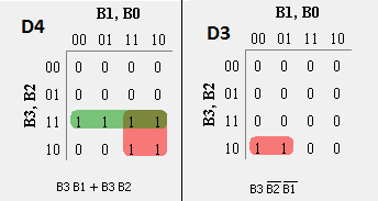
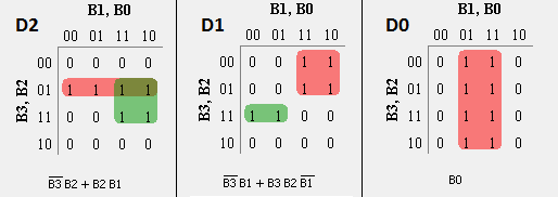
- To obtain these equations, Karnaugh-Map method is again used.
- For each BCD output D4, D3, D2, D1 and D0, write Karnaugh-Map.
- From the K-Map, obtaining a simplified expression for each BCD output in terms of Binary inputs.
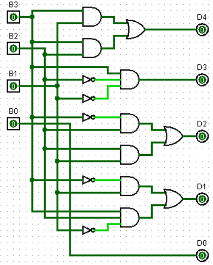
- Realize the code converter using the Logic Gates.
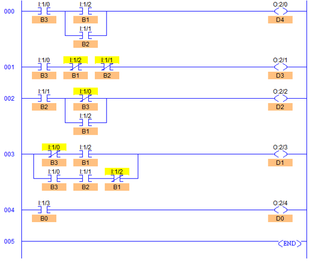
- And from the same simplified expressions, draw a Ladder Diagram to obtain BCD output in terms of Binary inputs.
Truth Table relating Binary to BCD
Decimal	Binary input	                BCD output
	B3	B2	B1	B0	D4	D3	D2	D2	D0
0	0	0	0	0	0	0	0	0	0
1	0	0	0	1	0	0	0	0	1
2	0	0	1	0	0	0	0	1	0
3	0	0	1	1	0	0	0	1	1
4	0	1	0	0	0	0	1	0	0
5	0	1	0	1	0	0	1	0	1
6	0	1	1	0	0	0	1	1	0
7	0	1	1	1	0	0	1	1	1
8	1	0	0	0	0	1	0	0	0
9	1	0	0	1	0	1	0	0	1
10	1	0	1	0	1	0	0	0	0
11	1	0	1	1	1	0	0	0	1
12	1	1	0	0	1	0	0	1	0
13	1	1	0	1	1	0	0	1	1
14	1	1	1	0	1	0	1	0	0
15	1	1	1	1	1	0	1	0	1
Boolean expression for each BCD bits can be written as
 D4= m(10, 11, 12, 13, 14, 15)
 D3= m(8, 9)
 D2= m(4, 5, 6, 7, 14, 15)
 D1= m(2, 3, 6, 7, 12, 13)
 D0= m(1, 3, 5, 7, 9, 11, 13, 15)
advertisement
advertisement
Realizing code conversion using Logic Gates
PLC Program
Here is PLC program to Implement Binary to BCD Converter, along with program explanation and run time test cases.
List of Inputs and Outputs
 B3=		I:1/0	(Input)
 B2=		I:1/1	(Input)
 B1=		I:1/2	(Input)
 B0=		I:1/3	(Input)
 D4=		O:2/0	(Output)
 D3=		O:2/1	(Output)
 D2=		O:2/2	(Output)
 D1=		O:2/3	(Output)
 D0=		O:2/4	(Output)
Ladder Diagram to obtain BCD output
Program Description
- D4 is MSB bit of BCD output.
- D3 is 2nd bit of BCD output and so are similarly D2, D1 and D0, 3rd, 4th and LSB of BCD output respectively.
- B3 to B0 are 4 Binary inputs which are converted into BCD numbers.
- RUNG000 is used for D4 bit and so on till RUNG004 which is used for LSB D0.
- As we apply any 4bit binary input, B3 to B0 are set to 1 such that D4 to D0 bits go high according to BCD patterns of the applied Binary input.
Runtime Test Cases
Hexa-
Decimal	Decimal	Binary input	                BCD output
		B3	B2	B1	B0	D4	D3	D2	D2	D0
0	0	0	0	0	0	0	0	0	0	0
1	1	0	0	0	1	0	0	0	0	1
2	2	0	0	1	0	0	0	0	1	0
3	3	0	0	1	1	0	0	0	1	1
4	4	0	1	0	0	0	0	1	0	0
5	5	0	1	0	1	0	0	1	0	1
6	6	0	1	1	0	0	0	1	1	0
7	7	0	1	1	1	0	0	1	1	1
8	8	1	0	0	0	0	1	0	0	0
9	9	1	0	0	1	0	1	0	0	1
A	10	1	0	1	0	1	0	0	0	0
B	11	1	0	1	1	1	0	0	0	1
C	12	1	1	0	0	1	0	0	1	0
D	13	1	1	0	1	1	0	0	1	1
E	14	1	1	1	0	1	0	1	0	0
F	15	1	1	1	1	1	0	1	0	1
Sanfoundry Global Education & Learning Series – PLC Algorithms.
advertisement
To practice all PLC programs, here is complete set of 100+ PLC Problems and Solutions.
advertisement
