This is a PLC Program for Heating Liquid in the Tank by Heater.
Problem Description
Controlling heating of Liquid in the tank using heater. Implement this process in PLC using Ladder Diagram programming language.
Problem Diagram
Diagram to control the heating of liquid in the tank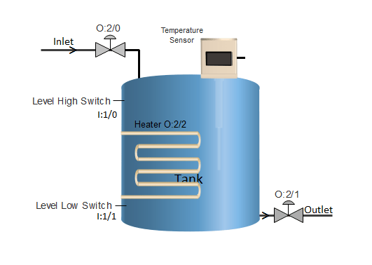
Problem Solution
- To detect high and low level of liquid in the tank, two level switches are used which gives output in digital terms, that is when corresponding levels are detected, it gives output high otherwise remain low.
- To control level of this system, Single Acting Piston valve can be used which has two states, either fully open or fully close and to heat the liquid, heater is used.
- Low Level Switch is mounted at the bottom of the tank and Level High switch is mounted at the side-upper most position.
- Heater is installed inside the tank and temperature sensor such as RTD or Thermocouple may be used to detect the temperature of liquid in the tank.
PLC Program
Here is PLC program for Heating Liquid in the Tank by Heater, along with program explanation and run time test cases.
List of Inputs and Outputs
 I:1/0	= Level High Switch	(Input)
 I:1/1	= Level Low Switch	(Input)
 O:2/0	= Inlet Valve		(Output)
 O:2/1	= Outlet Valve		(Output)
 O:2/2	= Heater		(Output)
 I:1/14	= Start			(Input)
 I:1/15	= Stop			(Input)
 N7:1	= Temperature Data	(Register)
Ladder Diagram to control this process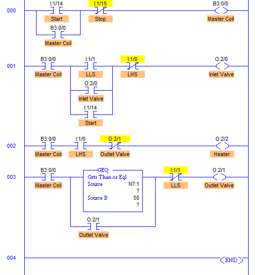
advertisement
advertisement
Program Description
- RUNG000 is simply for latching a coil and master start-stop buttons.
- RUNG003 is to control the outlet valve through O:2/1. This is done when Temperature is above 50°C. When temperature is greater than 50°C, outlet valve starts draining the liquid. XIO of Level Low Switch is connected in series so that when Level Low is detected, it goes true closing the outlet valve.
- Similarly in RUNG001, it works exactly same. It is energized when Level Low is detected. The only difference in RUNG001 is that extra I:1/14 contact in parallel with LLS.
- Suppose when the system is started and the tank is partially filled, neither LHS nor LLS is detected, in this case heater output does not get energized and heating is not controlled.
- To eliminate this error, I:1/14 (Start) is connected in parallel to LLS I:1/1 contact. This checks if LHS (I:1/0) is detected or not. If LHS is not detected, then it opens the inlet valve until LHS is detected and heating is started.
- In RUNG002, heater coil O:2/2 energizes when LHS I:1/0 is detected and heating is started. This is done until temperature reaches 50°C, O:2/1 is energized de-energizing O:2/2 which in turn stops heating.
Runtime Test Cases
Inputs	                 Outputs  	Physical Elements
I:1/1 = 1	         O:2/0 = 1	Open Inlet Valve, Close Outlet Valve
I:1/1 = 0, I:1/0 = 0	 O:2/0 = 1	None detected, Open Inlet Valve
I:1/0 = 0 & Temp. < 50°C O:2/2 = 1	Heater ON
Temp. ≥ 50	         O:2/1 = 1	Open Outlet Valve
O:2/1 = 1	         O:2/2 = 0	Heater OFF
Sanfoundry Global Education & Learning Series – PLC Algorithms.
To practice all PLC programs, here is complete set of 100+ PLC Problems and Solutions.
