This is a PLC Program to Heat the Liquid in Tank by Steam Flow.
Problem Description
Heating of the liquid in the tank is to be performed. To heat this liquid, steam flow is controlled. If the temperature is detected less than the set point, increase the steam flow and vice-versa. Implement automation of this process in PLC using Ladder Diagram programming language.
Problem Diagram

Problem Solution
- To detect temperature, RTD PT100 is used. This RTD has a range from -200°C to 650°C.
- Let’s say that the temperature of liquid in the tank is to be maintained at 100°C. Calibrate RTD to operate in this range.
- RTD PT100 has a resistance of 100Ω when it is at 0°C and 138.4Ω when at 100°C.
- Calibrate 4-20mA output such that when input is 0°C, it gives 4mA output and when it is 100°C, it gives output 20mA.
- Feed this data to Analog Input Module of PLC. Input module converts 4-20mA into equivalent 0000h to FFFFh hex number. This means when temperature is 0°C, data stored in the register is 0000 0000 0000 0000, and when output is 100°C, data stored in register is 1111 1111 1111 1111.
- Analog Output module converts this data into equivalent 4-20mA which is then converted into 3-15psi to operate control valve.
- One more method to solve this problem is by calculating Output in terms of 4-20mA for -200°C-650°C that when -200°C, it gives 4mA and when 650°C, it gives 20mA.
- But then this would not be precise control action because data conversion gives minor errors while performing conversion.
PLC Program
Here is PLC program to Heat the Liquid in Tank by Steam Flow, along with program explanation and run time test cases.
List of Inputs and Outputs
 I:1/0	= Start						(Input)
 I:1/1	= Stop						(Input)
 O:2/0	= Mater Coil					(Output)
 O:4	= Output to I-P converter			(Output)
 O:6	= Display					(Output)
 N7:0	= Register input data				(Register)
 N7:1	= answer of division by total range		(Register)
 N7:2	= Answer after multiplied by the set point	(Register)
 N7:3	= Convert set point as maximum value		(Register)
 N7:4	= Conversion to display temperature		(Register)
 I:3	= Input data (4-20mA)				(Input)
 N7:0	= Register input data				(Register)
Ladder Diagram when uncalibrated Transmitter is used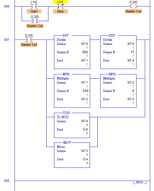
Ladder Diagram when transmitter is calibrated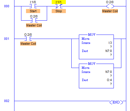
advertisement
advertisement
Program Description
- RUNG001 comprises all the conversion needed to control level of the tank.
- Output of transmitter is in current signals which is 4-20mA.
- When output is 4mA, Analog Input Module converts it into 16bit equivalent hex numbers. Hence when input to Analog module is 4mA, it stores 0000h into register and when 20mA, it stores FFFFh into register. Here register N7:0.
- Temperature range of RTD PT100 is -200°C-650°C. By converting it into equivalent hex, change in value per centimeter is 77.
- Value of N7:1 is then multiplied with the preset value of liquid temperature. That is here 300°C.
- This multiplication is stored into N7:2 register. This gives data which is again multiplied by 6 and stored in register N7:3 which gives full output when preset is reached. Digital to Analog conversion of value stored in N7:3 is performed inside the processor and equivalent mA current is received from terminal O:4.
- Current to Pneumatic converter then converts current signals into equivalent 3-15psi pneumatic signal and adjusts valve opening.
- In other method, when transmitter is calibrated, transmitter is tested in the laboratory and calibrated such that at 0°C, it gives output 4mA and at 100°C it gives 20mA.
- This 4-20mA can be directly converted into hex from 0000h to FFFFh. Then programming would be to just move this converted data into output which again converts 0000h-FFFFh into 4-20mA equivalent to actuate control valve.
Runtime Test Cases
Input	                 Output	        Valve percentage open
N7:0 = 0000h	         O:4 = 0000h	Valve Fully Open
N7:0 = 6946h (Set Point) O:4 = FFFFh	Valve Fully Closed
N7:0 = 3900h	         O:4 = 6940h	Valve 47% Closed
Sanfoundry Global Education & Learning Series – PLC Algorithms.
To practice all PLC programs, here is complete set of 100+ PLC Problems and Solutions.
