This is a PLC Program to Generate Outputs Based on Equations.
The following calculation will be made when input I:1/0 is true.
x=2^y √(2+Sin y)
If the result x is between 1 and 10 then the Output 0 will be turned on. The value of x will be output as an Analog voltage. Perform this operation in PLC using Ladder Diagram programming language.
- Perform tasks individually as defined below.
- Assign integer number addresses to store the 16/32bit data into registers.
- Use this addresses in the mathematical instructions as Source and Destination.
- Use XPY (X to power Y) instruction to find the input 2y.
- Use SIN instruction to find Sin y. Add this with 1 by using ADD instruction.
- Square Root this 1 + Sin y by using SQR instruction and multiply the output of XPY and SQR.
- Compare this data with the lower and upper limit and control output.
Here is PLC program to Generate Outputs Based on Equations, along with program explanation and run time test cases.
List of Inputs and Outputs
 I:1/0	= Start Input					(Input)
 N7:0	= Y input to SIN function			(Input)
 N7:1	= Sin Y operation data				(Input)
 N7:4	= Numeric Value “2” (To perform 2+Sin y)	(Input)
 N7:5	= Output of addition 2+Sin Y			(Input)
 N7:6	= Square Root of 2+Sin Y			(Input)
 N7:4	= Numeric Value “2” (To perform 2y)		(Input)
 N7:3	= Output of X to power Y (2y)			(Input)
 N7:7	= Lower Limit (01)				(Input)
 N7:8	= Higher Limit (10)				(Input)
 O:6	= Output x, multiplication of N7:6 & N7:3	(Output)
 O:0	= Output 0					(Output)
Ladder Diagram to obtain output of this mathematical equation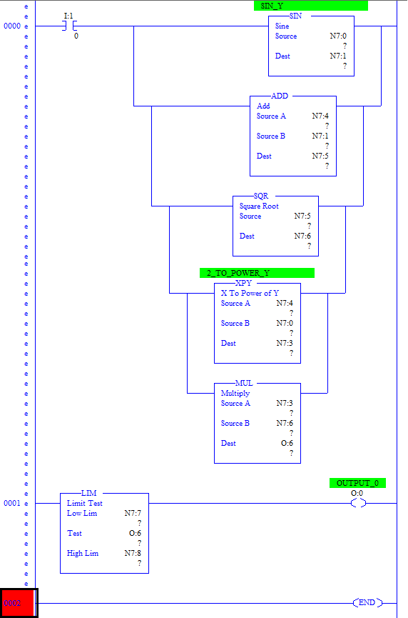
- As we can see, step by step procedure is done.
- Output of individual operations are first obtained.
- Output of all these data are stored into Integer Registers.
- Operation starts from the smallest function as shown in the RUNG0000 that first Sin Y(N7:0) is obtained, then Sin Y is added with the integer 2.
- Output of this 2+Sin Y is then square rooted using SQR instruction and result is stored into the register N7:6.
- Then 2y is performed. This is obtained by using XPY (X to power Y) instruction where X is N7:4 (digit 2) and Y is N7:0 (y).
- Output of this both are Multiplied to finally obtain the output of the equation X (O:6).
- LIM instruction is then used to compare output of the equation with its lower limit and upper limit. Accordingly output is generated.
- If O:6 is between 1 to 10, output O:0 energizes turning ON the Output 1.
You can check output by varying y (N7:0) input.
This program is tested and performed using RSLogix 500 Pro by Rockwell Automation.
Sanfoundry Global Education & Learning Series – PLC Algorithms.
To practice all PLC programs, here is complete set of 100+ PLC Problems and Solutions.
