This is a PLC Program to Drain Two Different Products from 2 Tanks.
Problem Description
There two different tanks which are to be operated. Draining of these two materials are controlled. Mixing in the ratio of 2:1 is to be done. Implement automation of this in PLC using Ladder Diagram programming language.
Problem Diagram
Diagram showing mixing of two materials continuously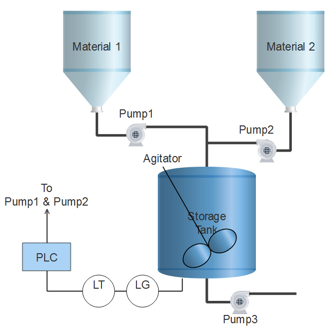
Problem Solution
- Level gauge is used to measure level of the storage tank continuously
- Level gauge is connected with Level Transmitter which converts corresponding level output in 4-20mA equivalent.
- Analog I/O Modules are chosen to deal with Analog signals.
- Centrifugal pumps are used to drain material from both the tanks at the same time.
- Height of storage tank is 5meters that is 500cm and the level which is to be maintained is 470cm.
- Calculate necessary conversions and use registers to store data and to do arithmetic operations.
PLC Program
Here is PLC program to Drain Two Different Products from 2 Tanks, along with program explanation and run time test cases.
List of Inputs and Outputs
 I:1/14	= Start							(Input)
 I:1/15	= Stop							(Input)
 O:2/15	= Master Coil						(Output)
 O:4	= Output to I-V converter of Pump1			(Output)
 O:6	= Output to I-V converter of Pump2			(Output)
 O:2/0	= Agitator to mix					(Output)
 I:3	= Input to which transmitter is connected		(Input)
 N7:0	= Register to store input data				(Register)
 N7:1	= answer of division by value change per centimeter	(Register)
 N7:2	= Multiplication answer					(Register)
 N7:3	= Division to obtain 2:1 ratio				(Register)
Ladder Diagram to control this mixing process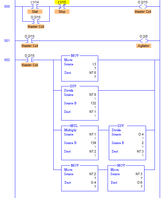
advertisement
advertisement
Program Description
- RUNG001 comprises all the conversion needed to control pumps.
- Output of transmitter is in current signals which is 4-20mA.
- When output is 4mA, Analog Input Module converts it into 16bit equivalent hex numbers. Hence when input at I:3 to Analog module is 4mA, it moves 0000h into register and when 20mA, it moves FFFFh into register. Here register N7:0.
- Here height of the tank is 5m or 500cm. By converting it into equivalent hex, change in value per centimeter is 132.
- Value of N7:0 is then multiplied with 139 because when Level reaches 470cm, output is F0C0h. So when output at 470cm is multiplied with 139, we get full FFFFh at N7:2 to operate pump2 in full speed and the pump2 half the speed of pump1 to achieve 2:1 mixing ration.
- This multiplication is stored into N7:2 register. Digital to Analog conversion of value stored in N7:2 is performed inside the processor and equivalent mA current is received from terminal O:4 and O:6.
- Current to Voltage converter then converts current signals into voltage signal and adjusts motor speed.
- Agitator with output O:2/0 is activated as soon as the Master Start PB is pressed.
Runtime Test Cases
Inputs	        Outputs                    Physical Elements
I:3 = F258h	O:4 = O:6 = 0000h	   Pump1 and Pump2 are off
I:3 = 792Ch	O:4 = 8000h, O:6 = 4000h   Pump1 = 4000RPM, Pump2 = 2000RPM
I:3 = 50C8h	O:4 = 5474h, O:6 = 2A3Ah   Pump1 = 2640RPM, Pump2 = 1320RPM
Sanfoundry Global Education & Learning Series – PLC Algorithms.
To practice all PLC programs, here is complete set of 100+ PLC Problems and Solutions.
