This is a PLC Program to Display Level of Three or More Tanks.
Problem Description
There are total 3 tanks of which level is being controlled. Display level of these tanks for 5secs of one by one. Implement this in PLC using Ladder Diagram programming language.
Problem Solution
- Continuous measurement is necessary in this case.
- Continuous level measuring devices such as Ultrasonic, Radar, Capacitive or Pressure gauge level sensor can be used.
- Output of these sensors are in analog form, so to deal with such analog data, analog modules are used in PLC.
- Analog modules convert analog signal into equivalent hex form.
- Convert this into level height in Meter or in any other parameter to display on the screen.
- Generate time base to MOV output storing register value to display address after converting into BCD equivalent.
- Use either number of timers or Sequential Output instruction to solve this problem.
PLC Program
Here is PLC program to Display Level of Three or More Tanks, along with program explanation and run time test cases.
List of Inputs and Outputs
 I:1		= Input from Tank 1				(Input)
 I:2		= Input from Tank 2				(Input)
 I:3		= Input from Tank 3				(Input)
 N7:0 and N7:1	= Store and  process data of tank 1		(Register)
 N7:2 and N7:3	= Store and process data of tank 2		(Register)
 N7:4 and N7:5	= Store and process data of tank 3		(Register)
 T4:0,T4:1,T4:2 = Timers to switch display data every 5secs	(Timers)
Ladder diagram showing conversion of input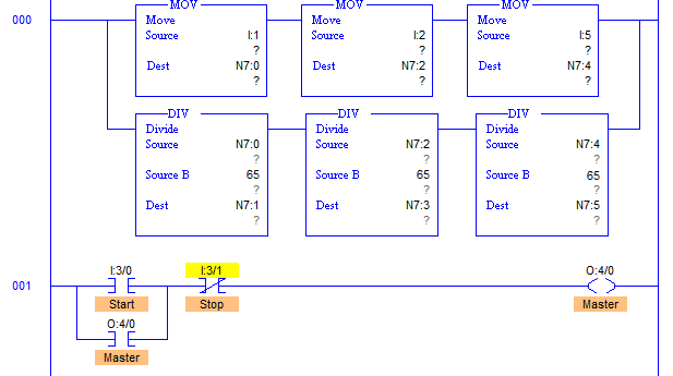
Ladder diagram to display level of different tanks on the same display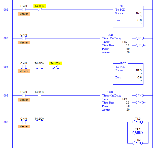
Program Description
- When level in tank rises, output of sensor increases accordingly.
- Suppose we have a tank with height 1000cm which is 10m.
- Converting 16bit data into 1000cm height, 65 is the answer which means, increment of 65 is obtained per centimeter rise in tank level.
- Input data from I:1 is continuously moved to N7:0 which means data in N7:0 register continuously varies.
- Value stored in N7:0 is divided by 65 and stored in register N7:1.
- Value stored in N7:1 register is first converted into equivalent BCD number before feeding it to display which is connected with output module at address O:6.
- Similarly output of remaining two tanks are processed.
- Work of timers here is just to change the input register address from which data is to be moved to output display after every 5secs.
- After completion of each cycle, timers are reset by RUNG008.
- Ladder diagram shows operation timers for just two tanks, one more timer should be added to display level of third tank.
- This problem can also be solved by using Sequential Output instruction SQO.
Runtime Test Cases
Inputs    	Outputs 	Physical Elements
O:2/0 = 1	O:6 = N7:1	Display level of Tank1
T4:0/DN = 1	O:6 = N7:3	Display level of Tank2
T4:1/DN = 1	O:6 = N7:5	Display level of Tank3
T4:2/DN = 1	O:6 = N7:1	Switch back to display level of Tank1
Sanfoundry Global Education & Learning Series – PLC Algorithms.
To practice all PLC programs, here is complete set of 100+ PLC Problems and Solutions.
advertisement
advertisement
