This is a PLC Program to Control Traffic Lights.
Problem Description
Implement controlling of Traffic Lights in PLC using Ladder Diagram programming language.
Problem Solution
- There are two methods to solve this problem. One is by using stack operation and the other one is by using sequencer output method.
- Sequencer output method is best suited for this problem since very less configuration is needed and program length is also reduced.
- In this method, we need to assign SQO instruction by configuring all the parameters given in the instruction.
- File, Mask, Dest, Control, Length and Positions are parameters which we need to configure.
- File : It is the starting address for the registers in the sequencer file.
- Mask : Mask is the bit pattern through which data flow happens from source to the destination address. If there is 1 in the masking, it passes values and if 0, it blocks the data flow.
- Dest : It is the address of the input to which the Sequencer Output instruction moves the data.
- Control : Is the address that contains the parameters with control information for the instruction. EN, DN and ER are bit which sets according to the status of sequencer output. EN and DN bits are set just as in timers. ER bit stands for Error bit, it is set when a negative position/length value is detected by the processor, or zero length value.
- Length : It is the number of steps of the sequencer file starting at position 1. Position 0 is the start-up position.
- Position: It indicated the steps that is desired to start the sequencer instruction. The start position is all zeros, this is represented as the neutral position; so no outputs will be turned ON in position 0.
- So to start the actual function of output sequence, Position 1 is determined as starting sequence while programming.
- Integers or Bit Registers are used as Destination Address.
PLC Program
Here is PLC program to Control Traffic Lights, along with program explanation and run time test cases.
List of Inputs and Outputs
 I:1/0	= Start 				(Input)
 I:1/1	= Stop					(Input)
 B3:0/0	= Latched Coil Bit			(Bit)
 T4:0	= Timer to update output sequence	(Timer)
 SQO	= Sequencer output			(Sequencer)
 O:2/0	= North-South Green Light		(Output)
 O:2/1	= North-South Yellow Light		(Output)
 O:2/2	= North-South Red Light			(Output)
 O:2/3	= East-West Green Light			(Output)
 O:2/4	= East-West Yellow Light		(Output)
 O:2/5	= East-West Red Light			(Output)
Ladder Diagram to control Traffic Light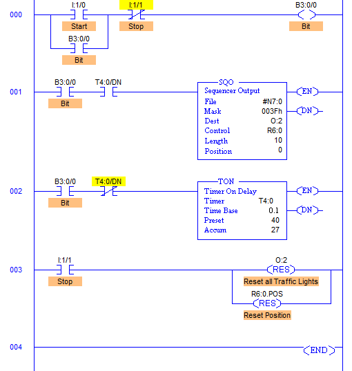
Program Description
- RUNG000 again here is for Master Start and Stop the process.
- File; #N7:0 and File length is 10, hence output sequence is varied from N7:0 to N7:10 with each input.
- Destination is set to O:2 hence with each transition, N7:0 to N7:10 are moved to O:2 with masking.
- O:2/0 to O:2/5 are used as the output address to Traffic Lights and hence Mask has value 003Fh which means data flow of N7:0/0…N7:10/0 to N7:0/5…N7:10/5 is passed and the remaining N7:0/6…N7:10/6 to N7:0/15…N7:10/15 are blocked.
- Control parameters are assigned to register R6:0.
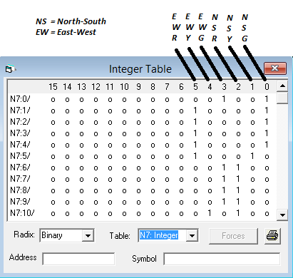
- Sequence of traffic lights to be operated are stored in the registers from N7:0 to N7:10 as following.
advertisement
advertisement
- Time base is set to 4secs, hence after every 4secs, output sequence is changed to its next register pattern outputs which is then transferred to O:2 and O:2/0 to O:2/5 are energized accordingly.
- As we can see, from N7:1 to N7:4 have the same bit pattern. So, these bits are set to 1 for 4 cycles that is 16secs. These bits are used for South-North Green light and East-West Red light.
- Similarly the entire sequence is followed.
- When Stop I:1/1 is pressed, Position is reset to 0 and all the outputs are de-energized.
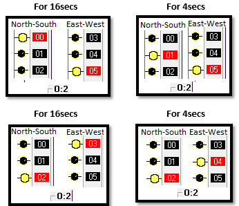
Runtime Test Cases
Sanfoundry Global Education & Learning Series – PLC Algorithms.
To practice all PLC programs, here is complete set of 100+ PLC Problems and Solutions.
