This is a PLC Program to Control Three Mixing Devices in a Processing Line.
Control three mixing devices in a process line. Two mixing devices are running in the parallel to each other. When any one of the mixing process stops, individual stop switches turn the third mixing device ON and the device operated by the stop button is stopped. Implement automation of this system in PLC using Ladder Diagram programming language.
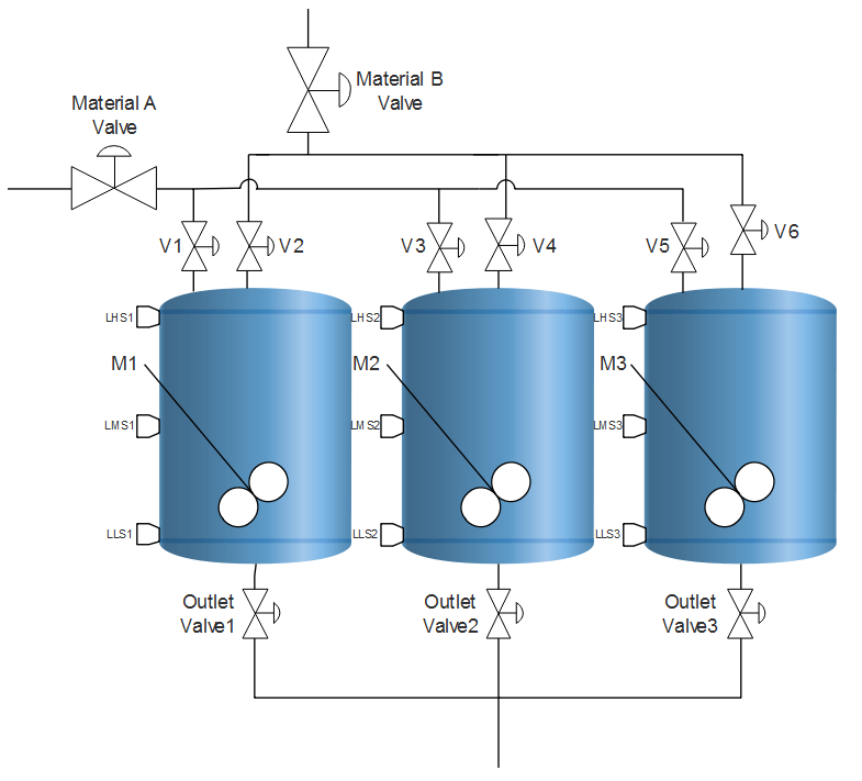
- Use limit switches, control valves and motor agitators separately for all three mixing tanks.
- The only common input to all these tanks is Material feeding by two valves.
- Use separate timers for each tank for mixing.
- First two tanks are tagged as primary mixing tanks and the third one is said to be secondary mixing tank.
- Use switches of stop buttons of both Primary mixing processes as an input to start the tank third to enter into the process sequence.
Here is PLC program to Control Three Mixing Devices in a Processing Line, along with program explanation and run time test cases.
List of Inputs and Outputs
 I:1/14			= Start 				(Input)
 I:1/15			= Stop					(Input)
 O:2/15			= Master Coil				(Output)
 I:1/0, I:1/5, I:1/7	= Level of Material B Switches		(Input)
 I:1/1, I:1/4, I:1/8	= Level of Material A switches		(Input)
 I:1/2, I:1/3, I:1/6	= Low Level Switch (empty tank)		(Input)
 O:2/0, O:2/4, O:2/8	= Inlet Valves to feed Material A	(Output)
 O:2/1, O:2/5, O:2/10	= Inlet Valves to feed Material B	(Output)
 O:2/2, O:2/6, O:2/9	= Agitator Motors M1, M2 and M3	        (Output)
 O:2/3, O:2/7, O:2/11	= Outlet Valves for product outlet	(Output)
 T4:0, T4:1, T4:2	= Timers to mix materials		(Timer)
Ladder Diagram for Mixing Tank 1
Ladder Diagram for Mixing Tank 2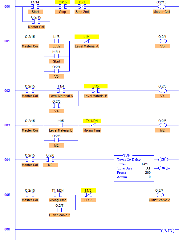
- RUNG000 contain master start/stop with address of Start PB I:1/14 and Stop PB I:1/15.
- RUNG001 is to operate V1 of Material A with address O:2/0. It is operated when Low Level of the tank 1 is detected by Level Low Switch1 I:1/2. And it is closed when Level Material A of tank 1 is detected by a switch with address I:1/1. Start PB is also connected in parallel with the LLS1, it is done so that when LLS1 or level of Material A is not detected, Inlet Valve is operated by Start PB.
- RUNG002 is to operate V2 of Material B with address O:2/1. It is opened when Material A is filled to its desired level (Level Material A). In other words, V2 of Material B is opened when Level of Material A is detected by I:1/1 and it is closed when Level of Material B of tank 1 is detected or Tank 1 is full.
Ladder Diagram for Standby/Secondary Mixing Tank (Tank 3)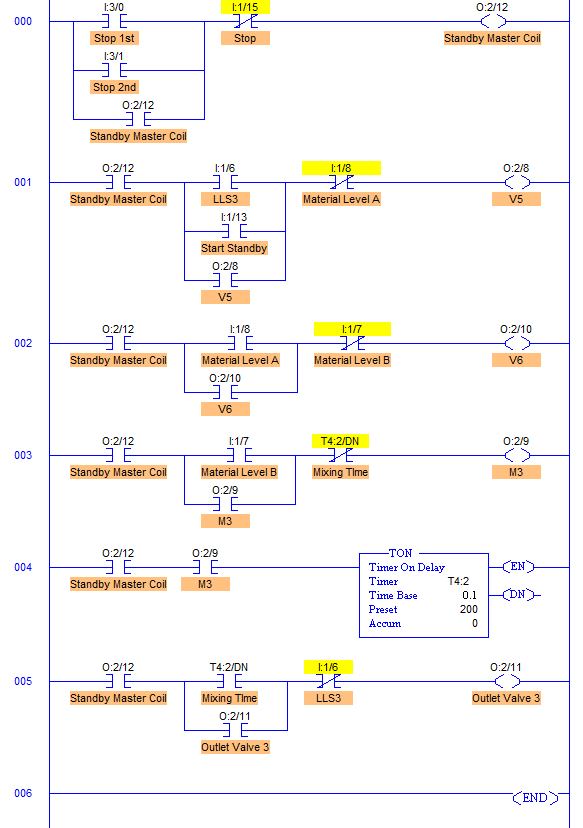
- RUNG003 & RUNG004 operates Agitator Motor M1 with address O:2/2. When the tank is full with Material A and B, Level High (Level Material B) of tank 1 is detected. This detection energizes O:2/2 and enables ON timer with address T4:0. Agitator Motor M1 is connected to the address O:2/2. So when O:2/2 energizes, Motor Agitator M1 starts the mixing process and mixes Material A and B for 20secs which is a preset of Timer ON. When Pre = Acc, T4;0/DN bit goes high turning off the agitator motor M1.
- RUNG005 is for Outlet Valve 1 with address O:2/3. It is operated when the entire mixing process is completed that is when Pre= Acc = 20secs. And this is closed when LLS is again detected.
- Similarly Mixing Process Tank 2 is operated.
Extra Inputs and Outputs for Standby Process
 I:3/0	= Individual Stop for tank 1 (Start Tank 3)	(Input)
 I:3/1	= Individual Stop for tank 2 (Start Tank 3)	(input)
- In Mixing Tank 3, when any of the Primary tanks Tank1 or Tank2 fails, operation of mixing tank 3 takes place.
- Input of this Mixing tank 3 is Individual stop buttons of Tank 1 and Tank 2 which has to be pressed in case of failure in either of the primary mixing tanks.
Inputs	                Outputs	                Physical Elements
I:1/2 = 1	        O:2/0 = 1	        Open V1
I:1/2 = 0 & I:1/1 = 0	O:2/0 = 1        	Open V1
I:1/1 = 1       	O:2/0 = 0       	Close V1
I:1/1 = 1         	O:2/1 = 1       	Open V2
I:1/0 = 1	        O:2/1 = 0               Close V2
I:1/0 = 1       	O:2/2 = 1        	Run Agitator Motor M1
T4:0/DN = 1       	O:2/2 = 0       	Stop Agitator Motor M1
T4:0/DN = 1     	O:2/3 = 1        	Open Outlet Valve1
I:1/2 = 1       	O:2/3 = 0       	Close Outlet Valve1

Similarly for Mixing Tank 2
I:3/0 = 1	        O:2/0 = 0, O:2/8 = 1	Start Process Tank 3, Open V5
I:3/1 = 1	        O:2/4 = 0, O:2/8 = 1	Start Process Tank 3, Open V5
Sanfoundry Global Education & Learning Series – PLC Algorithms.
To practice all PLC programs, here is complete set of 100+ PLC Problems and Solutions.
