This is a PLC Program to Control Lights in a Sequence (2).
Problem Description
Implement controlling of various lights in PLC using Ladder Diagram programming language using Bit Shift Registers.
Problem Solution
- Define order of lights.
- Use Bit Shift Registers to implement any sequence of lights.
- Double check if the order of light is made correctly and connections are made properly.
- Use latching coil for Master Start and Stop for prevention against malfunctioning.
- 0.1 Time Base function availability is useful to shift register bits very quickly.
- By using this, we can make lights blink.
- Check if bit addresses provided to Light output addresses are correctly chosen or not.
- Provide 16bit of length to Bit Shift Register, by adding this total 16 number of lights can be controlled.
- This limitation can be overcome by using more than one registers or with same length, more than one shift registers.
PLC Program
Here is PLC program to Control Lights in a Sequence, along with program explanation and run time test cases.
List of Inputs and Outputs
 I:1/0	= Master Start			(Input)
 B3:0	= Altering Register		(Output Register)
 R6:0	= Control Register		(Storing Register)
 R6:0/UL= Used for Wraparound operation	(Unload Bit)
 B3:0/0	= Bit input to Output 0		(Input Bit)
 O:2/0	= Output 0			(Output)
 B3:0/1	= Bit input to Output 1		(Input Bit)
 O:2/1	= Output 1			(Output)
 B3:0/2	= Bit input to Output 2		(Input Bit)
 O:2/2	= Output 2			(Output)
 B3:0/3	= Bit input to Output 3		(Input Bit)
 O:2/3	= Output 3			(Output)
 T4:0	= Timer	to shift bits		(Timer)
Ladder Diagram to solve this problem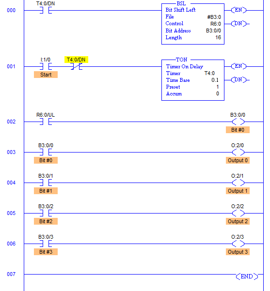
Program Description
- Here as it can be observed in the Ladder Diagram, Outputs are controlled by the bits set in the register B3:0.
- This outputs are controlled in accordance to shifting of bits from Right to Left.
- This shifting is controlled by Timer T4:0.
- Timer is set to auto reset mode by setting XIO T4:0/DN bit of the same timer to its input.
Master Start is included as well. This controls the entire process. This has to be a toggle switch otherwise latching rung is used in case Push Buttons are available and one more Stop PB must be added to Master Stop. - Whenever Timer Done bit is set, that bit sends False to True signal to Bit Shift Register which performs Shifting of bits to Left.
- Time delay is 0.1secs here, so that shifting is real quick.
- Length indicates the number of bits to be shifted, or the file length in, in bits.
- The Last bit is shifted out of the array and stored in the unload bit, R6:0/UL. The status that was previously in the unload bit is lost. So for wraparound condition, last bit of the array B3:0/0 is set to the position to the UL bit.
- After every 0.1secs, bits are shifted and orders outputs are controlled.
- The sequence of this outputs can be set by setting sequence of bits in the register B3:0 manually or automatically storing sensors’ outputs.
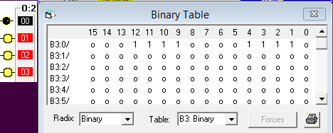
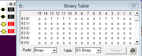
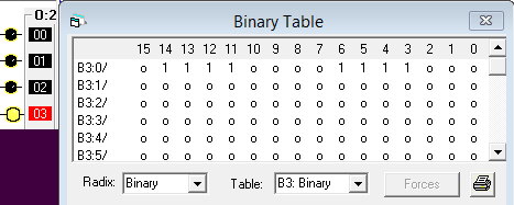
Runtime Test Cases
- Bits are shifted and Outputs are changed after every 0.1secs.
- Outputs are true in the sequence and go false in the same sequence if this bit pattern in the Register B3:0 is followed.
- You can set your own pattern and operate outputs accordingly.
advertisement
advertisement
Sanfoundry Global Education & Learning Series – PLC Algorithms.
To practice all PLC programs, here is complete set of 100+ PLC Problems and Solutions.
