This is a PLC Program to Control Lights in a Sequence (1).
Problem Description
Implement controlling of various lights in PLC using Ladder Diagram programming language using timers. Retentive Timer is suggested to use.
Problem Solution
- Define order of lights.
- Provide timers to lights, to each individually if necessary.
- Reset timers automatically or use reset coil to reset timers.
- Double check if the order of light is made correctly and connections are made properly.
- Use latching coil for Master Start and Stop for prevention against malfunctioning.
- 0.1 Time Base function availability is useful to turn ON and OFF a light.
- By using this, we can make lights blink.
- This is one method to solve this problem by using timers.
- Retentive Timers have a capability of storing the previous values at which timer was stopped or input was withdrawn.
- Hence Retentive Timer RTO can be used here so that in case of power failure, program can be restarted from where it was left previously.
PLC Program
Here is PLC program to Control Lights in a Sequence, along with program explanation and run time test cases.
List of Inputs and Outputs
 I:1/0	= Master Start			(Input)
 I:1/1	= Master Stop			(Input)
 O:2/15	= Master Coil			(Output)
 O:2/0	= Output 0			(Output)
 O:2/1	= Output 1			(Output)
 O:2/2	= Output 2			(Output)
 O:2/3	= Output 3			(Output)
 O:2/4	= Output 4			(Output)
 O:2/5	= Output 5			(Output)
 T4:0 	= Timer for Outputs 0 & 1	(Timer)
 T4:1	= Timer	for Outputs 2 & 3	(Timer)
 T4:2	= Timer for Outputs 4 & 5	(Timer)
 -(Res)-= Reset coil to reset timers	(Output)
Ladder Diagram to control sequence of lights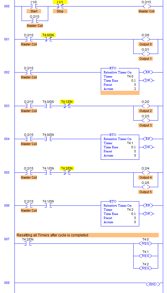
Program Description
- This program is just a simple combination of Timers and Outputs.
- The only difference here is that Retentive Timer is used instead of Timer ON TON or Timer OFF TOF.
- Various outputs Output 0 to 5 are used and made a pair of two outputs.
- One timer is provided to each pair of 2 outputs. Timers DN bits are used to Turn ON and OFF lights.
- The only difference here in this program is that Retentive Timers are used so that when Input is withdrawn or power fails, Timers do not reset itself because this Timer has a capability of storing last accumulated value and hence when again input is given, the program starts from where it was left previously.
- Simply time delay of 0.5 is generated here for each pair of lights.
Runtime Test Cases
Simple Lights’ Sequence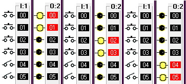
advertisement
advertisement
Sanfoundry Global Education & Learning Series – PLC Algorithms.
To practice all PLC programs, here is complete set of 100+ PLC Problems and Solutions.
