This is a PLC Program to Call a Subroutine for a Different Process.
Problem Description
Add temperature outputs of two temperature transmitters and display the total temperature. Update display every 10 seconds when this system is active using Subroutine program.
Problem Solution
- Using subroutine has an advantage that process is not affected by any other data in subroutine program unless and until the subroutine is called.
- This is very useful in displaying various data on the same display with a particular time delay.
- For example, we can use the same display to show Pressure readings for the first 5 seconds and Temperature reading for the next five seconds and so on.
- When we use subroutine instruction, Subroutine address must be same in JSR instruction of main program and RET instruction of subroutine program.
PLC Program
Here is PLC program to Call a Subroutine for a Different Process, along with program explanation and run time test cases.
List of Inputs and Outputs
 I:1/0	     = Start						(Input)
 I:1/1	     = Stop						(Input)
 O:2/0	     = Master Coil					(Output)
 T4:0	     = Time delay to update data			(Timer)
 O:6	     = Display address					(Output)
 N7:0 & N7:1 = Temperature data of transmitters 		(Register)
 T4:0/DN     = Update display calling Subroutine, reset timer	(Timer Bit)
 U:3	     = Address of Subroutine			        (Subroutine)
Ladder Diagram to call subroutine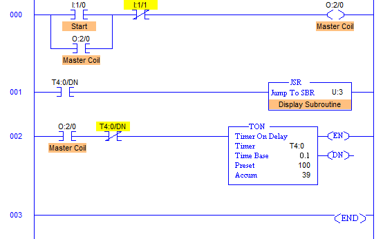
Program Description
- Main program comprises of simple Master Coil rung, rung for timer and rung to call subroutine.
- When Start PB I:1/0 is pressed, Master coil energizes and the TON timer T4:0 is enabled.
- After 10 seconds when PRESET=ACCUMULATOR, T4:0/DN bit goes high calling subroutine.
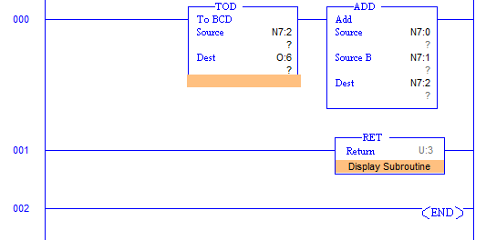
- Subroutine has a program that adds two data from addresses N7:0 and N7:1 which are outputs from Temperature transmitters. These outputs are added and output of addition is converted into BCD and sent to address O:6 which is connected to Display.
- Output data are in Hexadecimal and Displays accept BCD inputs. So TOD instruction is used here to convert data of temperature addition to BCD.
- T4:0/DN is also used as an XIO input to Timer itself, hence it automatically resets to 0 whenever preset and accumulator values are equal or in other words, it updates the display every 10secs resetting timer.
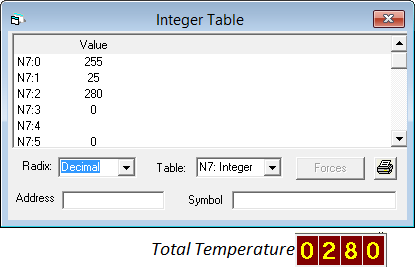
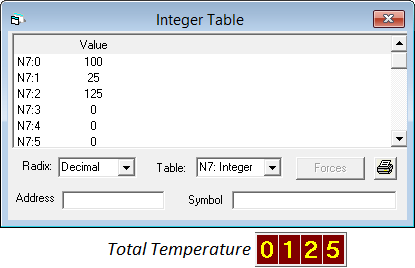
Runtime Test Cases
Display value is modified every 10secs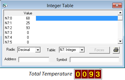
advertisement
advertisement
Sanfoundry Global Education & Learning Series – PLC Algorithms.
To practice all PLC programs, here is complete set of 100+ PLC Problems and Solutions.
