This set of Electrical Measurements & Measuring Instruments Multiple Choice Questions & Answers (MCQs) focuses on “Measurement of Low Resistance”.
1. Low resistance refers to _________
a) resistances of the order of 1ῼ
b) resistances of the order of 1kῼ
c) resistances of the order of 1mῼ
d) resistances of the order of 1Mῼ
View Answer
Explanation: Low resistance refers to resistance of the order of 1ῼ or less than that. Medium resistances range from above 1ῼ to a few kῼ. Any resistance value greater than a few kῼ is known as high resistance.
2. What is the significance of measuring low resistances?
a) voltage drop across the circuit is high
b) contact and lead resistances are appreciable
c) there is no power loss
d) no current flows through the bridge circuit
View Answer
Explanation: When measuring low resistances of the order of 1 ῼ or even less, lead and contact resistances of the order of even 0.002 ῼ cannot be neglected. High currents flow through low resistance circuits.
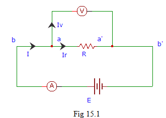
3. Fig 15.1 represents?
a) construction of medium resistance
b) construction of high resistance
c) construction of low resistance
d) construction of very low resistance
View Answer
Explanation: Fig 15.1, illustrates the construction of low resistance. A is an ammeter used to measure current through the circuit, while V is the voltmeter used to measure voltage.
4. How is the voltage drop across a low resistance related to lead resistance?
a) it contains contact resistance
b) it depends on the magnitude of voltage drop
c) it depends on the type of null detector used
d) It does not contain any contact resistance
View Answer
Explanation: The voltage drop measured across a low resistance does not contain any contact and lead resistances of the components and is independent of it.
5. Which is not a source of error in the measurement of low resistance?
a) contact resistance drops at the leads
b) thermal e.m.f
c) temperature effect
d) power dissipation through the circuit
View Answer
Explanation: As the current flowing through a low resistance circuit is low, the voltage drop across the terminals due to contact and lead resistances is negligible. Thermal e.m.f occurs in a circuit when its temperature increases due to high current flow.
6. Which is the most popular method for measuring low resistance?
a) ammeter-voltmeter method
b) potentiometer method
c) kelvin double bridge method
d) ducter ohmmeter method
View Answer
Explanation: Kelvin’s double bridge is used for the measurement of low resistances of the order of 1ῼ or less. Ammeter voltmeter method is used for the measurement of current flowing through and the voltage across the circuit.
7. How is the contact resistance related to the circuit while measuring a low resistance?
a) independent of the type of resistance
b) it is negligible
c) depends on the e.m.f source
d) it is very high
View Answer
Explanation: The contact and lead resistances form a part of the circuit whose resistance is very high. As a result the contact and lead resistances are usually neglected compared to the high resistance value.
8. In fig 15.1, the terminals aa’ are used for _________
a) measuring the current flow through the circuit
b) measuring the power dissipation of the circuit
c) measuring the resistance of the circuit
d) measuring the voltage drop across the resistance
View Answer
Explanation: The terminals aa’ are used for the measurement of the voltage drop across the resistance R. An voltmeter V is connected across the terminals aa’.
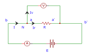
9. In the following figure, what is the value of I?
a) I = IV + Ir
b) I = IV – Ir
c) I = IV Ir
d) I = IV ⁄ Ir
View Answer
Explanation: By applying Kirchhoff’s current law at the node N from fig we get,
I = IV + Ir
where,
I is the total series current flowing through the circuit
Iv is the current flowing through the voltmeter
Ir is the current flowing through the resistance R.
Sanfoundry Global Education & Learning Series – Electrical Measurements.
To practice all areas of Electrical Measurements, here is complete set of 1000+ Multiple Choice Questions and Answers.
If you find a mistake in question / option / answer, kindly take a screenshot and email to [email protected]
