This set of Digital Signal Processing Multiple Choice Questions & Answers (MCQs) focuses on “Structures for IIR Systems”.
1. If M and N are the orders of numerator and denominator of rational system function respectively, then how many multiplications are required in direct form-I realization of that IIR filter?
a) M+N-1
b) M+N
c) M+N+1
d) M+N+2
View Answer
Explanation: From the direct form-I realization of the IIR filter, if M and N are the orders of numerator and denominator of rational system function respectively, then M+N+1 multiplications are required.
2. If M and N are the orders of numerator and denominator of rational system function respectively, then how many additions are required in direct form-I realization of that IIR filter?
a) M+N-1
b) M+N
c) M+N+1
d) M+N+2
View Answer
Explanation: From the direct form-I realization of the IIR filter, if M and N are the orders of numerator and denominator of rational system function respectively, then M+N additions are required.
3. If M and N are the orders of numerator and denominator of rational system function respectively, then how many memory locations are required in direct form-I realization of that IIR filter?
a) M+N+1
b) M+N
c) M+N-1
d) M+N-2
View Answer
Explanation: From the direct form-I realization of the IIR filter, if M and N are the orders of numerator and denominator of rational system function respectively, then M+N+1 memory locations are required.
4. In direct form-I realization, all-pole system is placed before the all-zero system.
a) True
b) False
View Answer
Explanation: In direct form-I realization, all-zero system is placed before the all-pole system.
5. If M and N are the orders of numerator and denominator of rational system function respectively, then how many memory locations are required in direct form-II realization of that IIR filter?
a) M+N+1
b) M+N
c) Min [M,N]
d) Max [M,N]
View Answer
Explanation: From the direct form-II realization of the IIR filter, if M and N are the orders of numerator and denominator of rational system function respectively, then Max[M,N] memory locations are required.
6. The basic elements of a flow graph are branches and nodes.
a) True
b) False
View Answer
Explanation: A signal flow graph provides an alternative, but an equivalent graphical representation to a block diagram structure that we have been using to illustrate various system realization. The basic elements of a flow graph are branches and nodes.
7. Which of the following is true for the given signal flow graph?
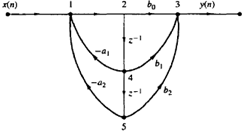
a) Two pole system
b) Two zero system
c) Two pole and two zero system
d) None of the mentioned
View Answer
Explanation: The equivalent filter structure of the given signal flow graph in the direct form-II is given by as
Thus from the above structure, the system has two zeros and two poles.
8. What are the nodes that replace the adders in the signal flow graphs?
a) Source node
b) Sink node
c) Branch node
d) Summing node
View Answer
Explanation: Summing node is the node which is used in the signal flow graph which replaces the adder in the structure of a filter.
9. The output signal of a system is extracted at a sink node.
a) True
b) False
View Answer
Explanation: The input to a system originates at a source node and the output signal is extracted at a sink node.
10. If we reverse the directions of all branch transmittances and interchange the input and output in the flow graph, then the resulting structure is called as ______________
a) Direct form-I
b) Transposed form
c) Direct form-II
d) None of the mentioned
View Answer
Explanation: According to the transposition or flow-graph reversal theorem, if we reverse the directions of all branch transmittances and interchange the input and output in the flow graph, then the system remains unchanged. The resulting structure is known as transposed structure or transposed form.
11. What does the structure given below represents?
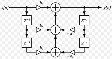
a) Direct form-I
b) Regular Direct form-II
c) Transposed direct form-II
d) None of the mentioned
View Answer
Explanation: The structure given in the question is the transposed direct form-II structure of a two pole and two zero IIR system.
12. The structure shown below is known as ____________
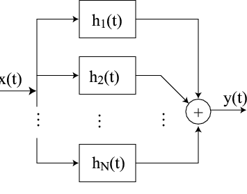
a) Parallel form structure
b) Cascade structure
c) Direct form
d) None of the mentioned
View Answer
Explanation: From the given figure, it consists of a parallel bank of single pole filters and thus it is called as parallel form structure.
Sanfoundry Global Education & Learning Series – Digital Signal Processing.
To practice all areas of Digital Signal Processing, here is complete set of 1000+ Multiple Choice Questions and Answers.
If you find a mistake in question / option / answer, kindly take a screenshot and email to [email protected]
