This set of Digital Electronics/Circuits Multiple Choice Questions & Answers (MCQs) focuses on “Combinational Circuits”.
1. Which of the circuits in figure (a to d) is the sum-of-products implementation of figure (e)?
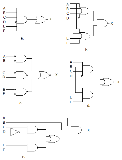
a) a
b) b
c) c
d) d
View Answer
Explanation: SOP means Sum Of Products form which represents the sum of product terms having variables in complemented as well as in uncomplemented form. Here, the diagram of d contains the OR gate followed by the AND gates, so it is in SOP form.
2. Which of the following logic expressions represents the logic diagram shown?
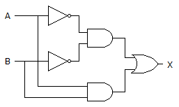
a) X=AB’+A’B
b) X=(AB)’+AB
c) X=(AB)’+A’B’
d) X=A’B’+AB
View Answer
Explanation: 1st output of AND gate is = A’B’
2nd AND gate’s output is = AB and,
OR gate’s output is = (A’B’)+(AB) = AB + A’B’.
3. The device shown here is most likely a ________
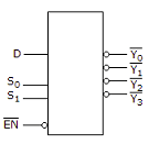
a) Comparator
b) Multiplexer
c) Inverter
d) Demultiplexer
View Answer
Explanation: The given diagram is demultiplexer, because it takes single input & gives many outputs. A demultiplexer is a combinational circuit that takes a single output and latches it to multiple outputs depending on the select lines.
4. What type of logic circuit is represented by the figure shown below?
a) XOR
b) XNOR
c) AND
d) XAND
View Answer
Explanation: After solving the circuit we get (A’B’)+AB as output, which is XNOR operation. Thus, it will produce 1 when inputs are even number of 1s or all 0s, and produce 0 when input is odd number of 1s.
5. For a two-input XNOR gate, with the input waveforms as shown below, which output waveform is correct?
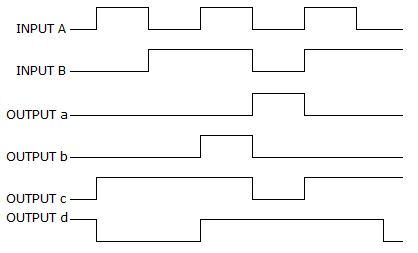
a) d
b) a
c) c
d) b
View Answer
Explanation: When both inputs are same then the o/p is high for a XNOR gate.
i.e., A B O/P
0 0 1
0 1 0
1 0 0
1 1 1.
Thus, it will produce 1 when inputs are even number of 1s or all 0s, and produce 0 when input is odd number of 1s.
6. Which of the following combinations of logic gates can decode binary 1101?
a) One 4-input AND gate
b) One 4-input AND gate, one inverter
c) One 4-input AND gate, one OR gate
d) One 4-input NAND gate, one inverter
View Answer
Explanation: For decoding any number output must be high for that code and this is possible in One 4-input AND gate, one inverter option only. We can have 1st, 2nd and 4th bit high and supplied to the AND gate and the 3rd bit (low) going through inverter 1st and then going to the AND gate. A decoder is a combinational circuit that converts binary data to n-coded data upto 2n outputs.
7. What is the indication of a short to ground in the output of a driving gate?
a) Only the output of the defective gate is affected
b) There is a signal loss to all load gates
c) The node may be stuck in either the HIGH or the LOW state
d) The affected node will be stuck in the HIGH state
View Answer
Explanation: Short to ground in the output of a driving gate indicates of a signal loss to all load gates. This results in information being disrupted and loss of data.
8. For the device shown here, assume the D input is LOW, both S inputs are LOW and the input is LOW. What is the status of the Y’ outputs?
a) All are HIGH
b) All are LOW
c) All but Y0 are LOW
d) All but Y0 are HIGH
View Answer
Explanation: In the given diagram, S0 and S1 are selection bits. So,
I/P S0 S1 O/P
D = 0 0 0 Y0
D = 0 0 1 Y1
D = 0 1 0 Y2
D = 0 1 1 Y3
Hence, inputs are S0 and S1 are Low means 0, so output is Y0 and rest all are HIGH.
9. The carry propagation can be expressed as ________
a) Cp = AB
b) Cp = A + B
c) All but Y0 are LOW
d) All but Y0 are HIGH
View Answer
Explanation: This happens in parallel adders (where we try to add numbers in parallel via more than one adders). A carry propagation occurs when carry from one adder needs to be forwarded to other adder and that second adder is holding the computation (addition) because carry from first adder has not come yet. So, there is a slight delay for second adder and this is known as carry propagation.
10. 3 bits full adder contains ________
a) 3 combinational inputs
b) 4 combinational inputs
c) 6 combinational inputs
d) 8 combinational inputs
View Answer
Explanation: Full Adder is a combinational circuit with 3 input bits and 2 output bits CARRY and SUM. Three bits full adder requires 23 = 8 combinational circuits.
Sanfoundry Global Education & Learning Series – Digital Circuits.
To practice all areas of Digital Circuits, here is complete set of 1000+ Multiple Choice Questions and Answers.
If you find a mistake in question / option / answer, kindly take a screenshot and email to [email protected]
- Apply for Electrical Engineering Internship
- Practice Electrical Engineering MCQs
- Check Digital Electronics Books
- Check Electrical Engineering Books
- Check Electronics & Communication Engineering Books
