This set of Analog Circuits Multiple Choice Questions & Answers (MCQs) focuses on “Diode Gates and Rectifiers”.
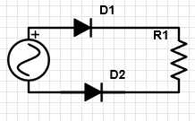
1. What is the logic gate implemented in the following circuit?

a) OR
b) AND
c) NOT
d) NOR
View Answer
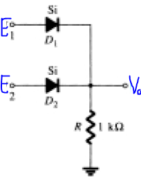
Explanation: In the given circuit, as a logic gate, E1 and E2 are digital inputs, 1 or 0. If the input is 1, the diode is forward biased and conducts, else it is reverse biased. So, the output is high whenever either of the input is high, or both of them are high, hence it acts as an OR gate.
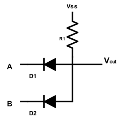
2. What is the logic gate implemented in the following circuit?
a) OR
b) AND
c) NOT
d) NOR
View Answer
Explanation: Whenever either diode is forward biased, there is a path for the current to flow out of and hence the output is zero. Thus if either A or B are 0, then output is zero. If however, both A and B are equal to VSS or more, then the diodes are reverse biased and output is available. Hence the circuit acts as an AND gate.
3. Which of the following statements best describes the reason for not using diodes to implement logic gates?
a) Diodes are expensive
b) Diodes are unreliable and less efficient
c) The diode circuits have limited range of operation
d) Diodes are bulky for a logic gate
View Answer
Explanation: The diode circuits are relatively less stable when compared to the transistor circuits, which are easy to tune in terms of stability and reliability.
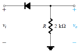
4. In the given circuit, what is the output V0 if E1 = 10V and E2 = 0V?
a) 0 V
b) 0.7 V
c) 10 V
d) 9.3 V
View Answer
Explanation: Here, current through the grounded branch = (10-0.7)/1k = 9.3 mA. Hence, voltage drop across the resistor=9.3 V. Hence, V0 = 9.3V.
5. In the given circuit, what is the ideal output V0 if E1 = 10V and E2 = 0V?

a) 0 V
b) 0.7 V
c) 10 V
d) 9.3 V
View Answer
Explanation: In an ideal diode, the voltage drop is zero. Hence, complete voltage 10V appears across the resistor and as the output too.
6. A 12 V, 50 Hz sine wave is fed to the given circuit as input? What is the output for 0.01s < t < 0.02s?
a) True
b) False
View Answer
Explanation: The given circuit is that of a half wave rectifier in which the diode remains in the off state for the negative half and conducts for positive half. During the time 0.01 sec to 0.02sec, the input 12sin(2π50t) is positive, hence a certain output not equal to zero is available.
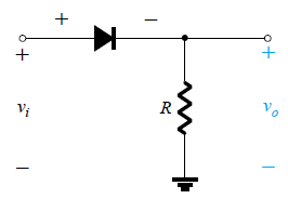
7. Which circuit has been represented in the associated circuit diagram?
a) Half wave rectifier
b) Full wave rectifier
c) NOT gate
d) AND gate
View Answer
Explanation: Both the diodes are similarly biased and are in series. Hence, they form a half wave rectifier.
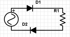
8. Which circuit has been represented in the associated circuit diagram?
a) Half wave rectifier
b) Full wave rectifier
c) NOT gate
d) AND gate
View Answer
Explanation: In the given circuit, when the diode D1 is on, diode D2 is off and vice versa. Hence, the upper diode conducts during the positive half of the input cycle and the lower diode conducts during the negative half of the input cycle and hence, it is a full wave rectifier circuit.
9. What is the value of DC equivalent output voltage for the given circuit, given that the input voltage is 20 Vp-p and 50 Hz and the diode is a silicon diode?
a) 2.9574 V
b) -2.9574 V
c) -3.125 V
d) 0 V
View Answer
Explanation: Vdc is given by 0.318(Vp). Here Vp = 10-0.7 V = 9.3 V and hence, Vdc = 0.318 x 9.3 V = 2.9574 V. Now, as the output Is non zero only for the negative half cycles of the input, Vdc = -2.9574 V.
10. Which of the following equations is correct for a full wave rectified output?
a) |Vdc| = 0.318 Vp
b) |Vdc| = 0.636 Vp
c) |Vdc| = 0.477 Vp
d) |Vdc| = 0.211 Vp
View Answer
Explanation: The output dc level of a half wave rectified wave is equal to 0.318 Vp. But, for a fully rectified wave, it becomes equal to 0.636 of the peak value.
11. Which of the following statements are true about the given circuit?
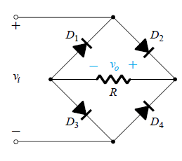
a) The circuit is that of a bridge rectifier
b) The PIV of the diode D1 must be greater than v0 for the circuit to function as a bridge rectifier
c) For silicon diodes, the value of v0=(vi-1.4) V
d) All of the mentioned
View Answer
Explanation: The circuit is that of a bridge rectifier. For proper functioning, the PIV of diodes must be at least greater than v0 and since, the current through any path flows through 2 diodes. There is a drop of 1.4 V.
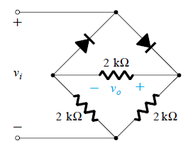
12. In the given circuit, what will be the nature of the output waveform?

a) Half rectified
b) Full rectified
c) Sinusoidal
d) DC
View Answer
Explanation: The right diode conducts during the positive half of the input cycle and the left diode conducts during the negative half of the input cycle. Hence, the output will be a fully rectified wave.
13. In the given circuit, what is the value of Vp for the output wave, if the input fed is 20 Vp-p?
a) 10 V
b) 9.3 V
c) 5 V
d) 4.7 V
View Answer
Explanation: As is clear from the circuit that v0 = 0.5 vi and hence peak value of the output wave is equal to half of the peak value of the input wave and hence Vp = 10/2 = 5 V.
Sanfoundry Global Education & Learning Series – Analog Circuits.
To practice all areas of Analog Circuits, here is complete set of 1000+ Multiple Choice Questions and Answers.
If you find a mistake in question / option / answer, kindly take a screenshot and email to [email protected]
