his set of Analog Circuits Multiple Choice Questions & Answers (MCQs) focuses on “Parallel Clipper Circuit with Reference Voltage-1”.
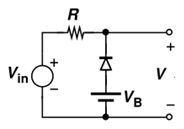
1. Which of the following graphs will be appropriate to describe output V of the circuit given below?
(The voltage VB is 1V and input to the circuit Vin is 5sint. The resistance R is 1K. Use constant voltage drop model for diode and take cut-in voltage as 0.7V)
a) 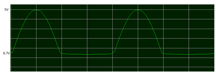
b) 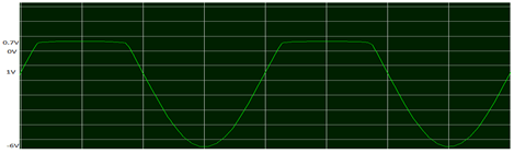
c) 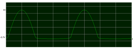
d) 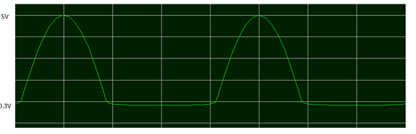
View Answer
Explanation: In the circuit VB is in the forward direction for diode. At positive cycle of Vin diode will be forward biased up to Vin = 0.3V. Up to 0.3V output is 0.3V and after this diode is reverse biased and output follows input. In negative cycle diode is always forward biased and output will be equal to 1-0.7 = 0.3V.
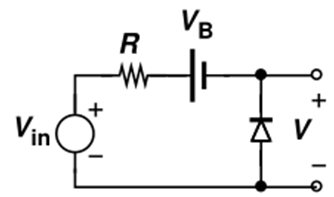
2. Which of the following graphs will be appropriate to describe output V of the circuit given below?
(The voltage VB is 1V and input to the circuit Vin is 5sint. The resistance R is 1K. Use constant voltage drop model for diode and take cut-in voltage as 0.7V)
a)
b)
c)
d)
View Answer
Explanation: In the circuit, diode is forward biased, whenever the voltage at the N side is negative, i.e, 5sint – 1 < 0. Whenever diode is forward biased, output voltage is 0.7V due to the constant voltage drop model. When the diode is reverse biased, the complete input 5sint – 1 is observed at the output side. So the output lies between 0.7V to 5sint-1V, i.e a maximum of 4V.
In the following diagram red represents input and green represents output.
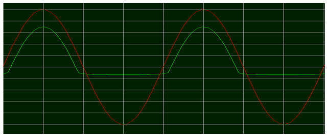
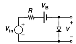
3. Which of the following graphs will be appropriate to describe output V of the circuit given below?
(The voltage VB is 1V and input to the circuit Vin is 5sint. The resistance R is 1K. Use constant voltage drop model for diode and take cut-in voltage as 0.7V)
a)
b)
c)
d)
View Answer
Explanation: In the circuit VB is in the reverse direction for diode. During positive cycle of input, when 5sint -1 > 0.7, then output voltage is 0.7V since the diode is forward biased. When 5sint-1<0, then output follows input since the diode is reverse biased. Thus minimum possible output is -5-1 = -6.
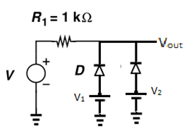
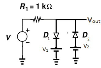
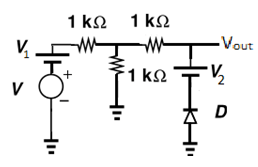
4. Which of the following graphs will be appropriate to describe output Vout of the circuit given below?
(The voltage V1 is 1V, V2 is 1V and input to the circuit V is 5sint. Assume both diodes are identical. Use constant voltage drop model for diode and take cut-in voltage as 0.7V)
a)
b)
c)
d)
View Answer
Explanation: In the circuit V1 and V2 are in the forward direction for diodes. Since these are parallel we can consider this as a single diode and source. At positive cycle of Vin diode will be forward biased up to Vin = 0.3V. Up to 0.3V output is 0.3V and after this diode is reverse biased and output follows input. In negative cycle diode is always forward biased and output will be equal to 1-0.7 = 0.3V.
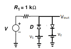
5. Which of the following graphs will be appropriate to describe output Vout of the circuit given below?
(The voltage V1 is 1V, V2 is 1V and input to the circuit V is 5sint. Assume both diodes are identical. Use constant voltage drop model for diode and take cut-in voltage as 0.7V)
a)
b)
c)
d)
View Answer
Explanation: In this circuit diodes are placed opposite to each other. So output will be determined by diode which is in forward bias. At negative cycle first diode will be forward biased hence output will be 0.3V. At positive cycle diode will be reverse bias up to 1.7V so input follows output and after this it is constant and equals to 1.7V.
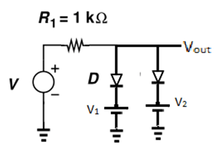
6. Which of the following graphs will be appropriate to describe output Vout of the circuit given below?
(The voltage V1 is 1V, V2 is 1V and input to the circuit V is 5sint. Assume both diodes are identical. Use constant voltage drop model for diode and take cut-in voltage as 0.7V)
a) 
b) 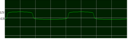
c) 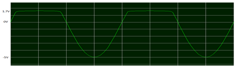
d) 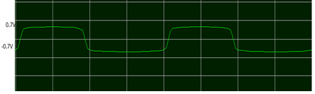
View Answer
Explanation: Since both diodes are in reverse mode with respect to V1 and V2, at negative V output follows input. At positive cycle up to 1.7V diodes are in reverse bias mode and after this they becomes forward biased and output becomes a constant and equals to 1.7V.
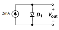
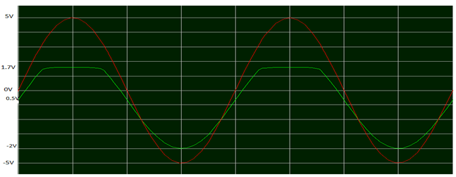
7. Which of the following graphs will be appropriate to describe output Vout of the circuit given below?
(The voltage V1 is 1V, V2 is 1.5V and input to the circuit V is 5sint. Assume both diodes are identical. Use constant voltage drop model for diode and take cut-in voltage as 0.7V)
a)
b)
c)
d)
View Answer
Explanation: To forward bias the first diode, input needs to be greater than 1.7V. Hence whenever input is greater than 1.7V, output is constant at 1.7V. When input is less than 0.8V, the second diode is forward biased. Between these values, output follows the input.
8. Which of the following graphs will be appropriate to describe output Vout of the circuit given below?
(The voltage V1 is 1V, V2 is 1V and input to the circuit V is 5sint. Use constant voltage drop model for diode and take cut-in voltage as 0.7V)
a) 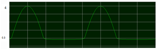
b)
c)
d)
View Answer
Explanation: At positive cycle of V, V1 opposes hence output will be 5sint-1. For negative half cycle of V, output will be 0.3V because diode is already in forward bias.
9. Which of the following graphs will be appropriate to describe output Vout of the circuit given below?
(The voltage V1 is 1V, V2 is 1V and input to the circuit V is 5sint. Use constant voltage drop model for diode and take cut-in voltage as 0.7V)
a) 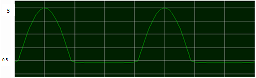
b)
c)
d) 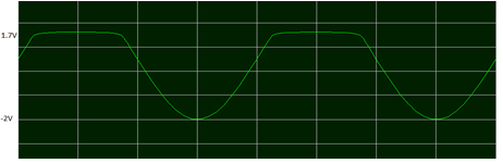
View Answer
Explanation: For negative half cycle diode is forward biased and hence output is 0.3V. For positive half cycle output will be (5sint+1)/2(Since voltage divided in between two 1K, third one has no effect). Hence maximum voltage will be 6/2 = 3V.
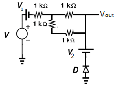
10. Which of the following graphs will be appropriate to describe output Vout of the circuit given below?
(The voltage V1 is 1V, V2 is 1V and input to the circuit V is 5sint. Use constant voltage drop model for diode and take cut-in voltage as 0.7V)
a)
b)
c)
d)
View Answer
Explanation: For negative half cycle of V and up to 3.4V in positive half cycle since diode is in reverse bias output will be (5sint-1)/2 Since voltage divided in between two 1K, third one has no effect). Hence minimum voltage will be -4/2 = -2V. After 3.4V output becomes 1.7V.
Sanfoundry Global Education & Learning Series – Analog Circuits.
To practice all areas of Analog Circuits, here is complete set of 1000+ Multiple Choice Questions and Answers.
If you find a mistake in question / option / answer, kindly take a screenshot and email to [email protected]
