This set of Analog Circuits Multiple Choice Questions & Answers (MCQs) focuses on “Parallel Clipper-1”.
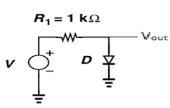
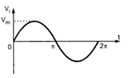
1. For a circuit given below, what will be the output if input signal is a sine wave shown below.
(Use ideal diode model of diode)
a) 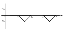
b) 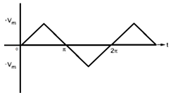
c) 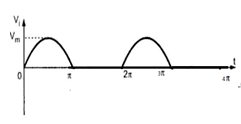
d) 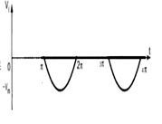
View Answer
Explanation: In this circuit of parallel clipper, diode conducts the half cycle when it is positive and the output will only contain negative half cycle. In this problem input is a sine wave, hence output will be negative half of sine wave.
2. For a circuit given below, what will be the output if input signal is a triangular wave shown below.
(Use ideal diode model of diode)
a)
b)
c)
d)
View Answer
Explanation: In this circuit of parallel clipper, diode conducts the half cycle when it is positive and the output will only contain negative half cycle. In this problem input is a triangular wave, hence output will be negative half of that wave.
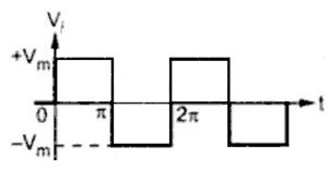
3. For a circuit given below, what will be the output if input signal is a square wave shown below.
(Use ideal diode model of diode)
a)
b) 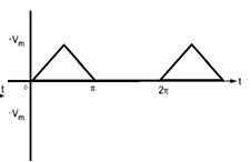
c) 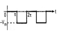
d) 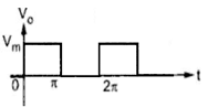
View Answer
Explanation: In this circuit of parallel clipper, diode conducts the half cycle when it is positive and the output will only contain negative half cycle. In this problem input is a square wave, hence output will be negative half of that wave.
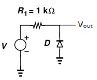
4. A simple circuit diagram for a parallel clipper is given below. What will be the approximate transfer characteristics of the circuit?
(Use ideal diode model of diode)
a) 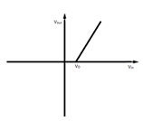
b) 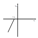
c) 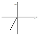
d) 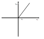
View Answer
Explanation: The above is a parallel clipper with an ideal diode model, so whenever the input is in its negative cycle, it will come as the output as the diode will then not conduct. When positive, diode conducts and output is zero.
5. For a circuit given below, what will be the output if input signal is a sine wave shown below.
(Use ideal diode model of diode)
a)
b)
c)
d)
View Answer
Explanation: In this circuit of parallel clipper, diode conducts whenever the input cycle is the negative half cycle and thus output will only contain positive half cycle. In this problem, input is a sine wave, hence output will be positive half of sine wave.
6. For a circuit given below, what will be the output if input signal is a triangular wave shown below.
(Use ideal diode model of diode)
a)
b)
c)
d)
View Answer
Explanation: In this circuit of parallel clipper, diode conducts whenever the input cycle is the negative half cycle and thus output will only contain positive half cycle. In this problem, input is a triangular wave, hence output will be positive half of that wave.
7. For a circuit given below, what will be the output if input signal is a square wave shown below.
(Use ideal diode model of diode)
a)
b)
c)
d)
View Answer
Explanation: In this circuit of parallel clipper, diode conducts whenever the input cycle is the negative half cycle and thus output will only contain positive half cycle. In this problem, input is a square wave, hence output will be positive half of that wave.
8. A simple circuit diagram for a serial clipper is given below. What will be the transfer characteristics of the circuit? (Use ideal diode model of diode)
a)
b)
c)
d)
View Answer
Explanation: For ideal diode, the above is a negative clipper. When the input cycle is negative, the diode conducts and no output is obtained. However, when input is positive, the diode is reverse biased and complete input is observed as output.
9. For a circuit given below, what will be the output if the input signal is a sine wave shown below.
(Use constant voltage drop diode model of diode)
a) 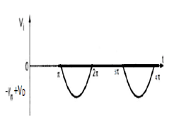
b) 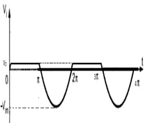
c) 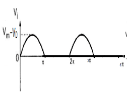
d) 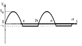
View Answer
Explanation: The above is a parallel clipper, which conducts when the input is negative and blocks signals when input is positive. Hence, when input is positive, it doesn’t conduct and complete input appears in output. When input is negative, the diode conducts, forward biased, and only the voltage drop of diode appears since it’s a constant voltage drop model.
10. For a circuit given below, what will be the output if input signal is a sine wave shown below.
(Use constant voltage drop diode model of diode)
a)
b)
c)
d)
View Answer
Explanation: The above is a parallel clipper, which conducts when the input is positive and blocks signals when input is negative. Hence, when input is negative, it doesn’t conduct and complete input appears in output. When input is positive, the diode conducts, forward biased, and only the voltage drop of diode appears since it’s a constant voltage drop model.
Sanfoundry Global Education & Learning Series – Analog Circuits.
To practice all areas of Analog Circuits, here is complete set of 1000+ Multiple Choice Questions and Answers.
If you find a mistake in question / option / answer, kindly take a screenshot and email to [email protected]
- Check Electrical Engineering Books
- Apply for Electrical Engineering Internship
- Practice Electrical & Electronics Engineering MCQs
- Practice Electrical Engineering MCQs
- Apply for Electrical & Electronics Engineering Internship
