This set of Analog Circuits Multiple Choice Questions & Answers (MCQs) focuses on “Load Line Analysis”.
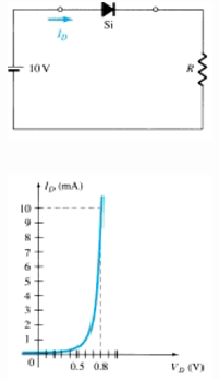
1. From the circuit and the diode characteristics given alongside, and assuming R=2k, what is the value of diode voltage at the operating point?
a) 0.78 V
b) 10 V
c) 0 V
d) 1v
View Answer
Explanation: On drawing the load line with the equation: VD = ED + IDRD, we get the operating point with the value of at voltage at around 0.7-0.8 V. Hence, VDq=0.78 V.
2. From the circuit and the diode characteristics given and assuming R=1k, what is the value of diode current at operating point?
a) 20 mA
b) 9.3 mA
c) 0 mA
d) 10 mA
View Answer
Explanation: On drawing the load line with the equation: VD = ED + IDRD, we get the operating point with the value of current at around 9.2-9.4 mA. Hence, IDq=9.3 mA.
3. From the circuit and the diode characteristics given and assuming R=1k, what is the value of voltage across the resistor at operating point?
a) 10 V
b) 0 V
c) 9.3 V
d) 10.7 V
View Answer
Explanation: We know that VR=IDR = 9.3 x 1 = 9.3 V.
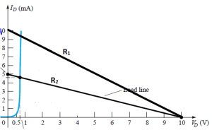
4. From the given load line characteristics, what is the relation between R1 and R2 , assuming constant source EMF?
a) R1 > R2
b) R1 = R2
c) R1 < R2
d) R1 >= R2
View Answer
Explanation: Here, the y-intercept=E/R hence, lower the y-intercept, higher the value of R, Hence, R1<R2
5. What is the change in voltage across the resistor when the load line is shifted from R1 to R2?
a) 0 V
b) 9.25 V
c) 10 V
d) 9 V
View Answer
Explanation: The value of voltage calculated across the resistor is calculated by E-VD, which is constant for both cases.
6. From the given load characteristics, what is the value of diode current at operating point for the characteristics of R2?
a) 9.3 mA
b) 4.6 mA
c) 0 mA
d) 10 mA
View Answer
Explanation: At the point of intersection, the value of current is around 4.6 mA.
7. From the given load characteristics, what is the value of diode voltage at operating point for the characteristics of R2?
a) 0 V
b) 10 V
c) 0.7 V
d) 1 V
View Answer
Explanation: At the point of intersection, the value of diode voltage is approximately 0.7 V.
8. Using the approximate equivalent model of a silicon diode and taking E=10 V and R=1k, what is the value of diode voltage at operating point?
a) 0.7 V
b) 0.3 V
c) 10 V
d) 9.3 V
View Answer
Explanation: In the approximate equivalent model, the diode voltage is fixed at the forward bias threshold voltage, which for a silicon diode is equal to 0.7 V
9. Using the approximate equivalent model of a silicon diode and taking E=10 V and R=1k, what is the value of diode current at operating point?
a) 9.25 mA
b) 10 mA
c) 0 mA
d) 9.5 mA
View Answer
Explanation: In the approximate equivalent model, the characteristic is assumed to be a vertical upward line at V=0.7 V. Hence, the current at point of intersection is determined to be 9.25 mA
10. Using the ideal diode model of a silicon diode and taking E=10 V and R=1k, what is the value of diode voltage at operating point?
a) 0.7 V
b) 0 V
c) 10 V
d) 0.3V
View Answer
Explanation: In ideal diode model, we take the forward threshold voltage to be zero. Hence the diode characteristic is represented as the upper half of the y-axis. Hence, VD = 0 V.
11. Using the ideal diode model of a silicon diode and taking E=10 V and R=1k, what is the value of diode current at operating point?
a) 9.25 mA
b) 10 mA
c) 0 mA
d) 9.5mA
View Answer
Explanation: In ideal diode model, we take the forward threshold voltage to be zero. Hence thee diode characteristic is represented as the upper half of the y-axis. Hence, ID = E/R = 10 mA.
12. The ideal diode model of a silicon semiconductor diode gives an error that is greater than that obtained in approximate equivalent model. Is the statement true or false?
a) True
b) False
View Answer
Explanation: In the ideal diode we assume the diode voltage as zero whereas in the approximate equivalent circuit model, we assume VD = 0.7 V and the actual value is somewhere about 0.75-0.8 V. Hence, approximate equivalent model is more accurate.
Sanfoundry Global Education & Learning Series – Analog Circuits.
To practice all areas of Analog Circuits, here is complete set of 1000+ Multiple Choice Questions and Answers.
If you find a mistake in question / option / answer, kindly take a screenshot and email to [email protected]
